| |
1-THE LAYERED MODEL 2- THE OSI MODEL 3-TYPES OF MEDIUM
4-IP ADDRESSING 5-PASSWORD RECOVERY
cours 1: The layered network model
Network models use layers to simplify the networking functions.
The separation of networking functions is called layering. To
understand the importance of layering, let's consider the OSI
reference model, a layered model for understanding and implementing
computer communications. By using layers, the OSI reference model
simplifies the tasks required for two computers to communicate
with each other.
Each layer can be focused on specific functions, thereby allowing
the networking designer to choose the right networking devices
and functions for the layer. In the OSI reference model, each of
the seven numbered layers indicate distinct functions. The reasons
for this division of network functions include the following:
 .Layers divide the aspects of network
operation into less complex elements.
.Layers define standard interfaces for
plug-and-play compatibility.
.Layers enable engineers to specialize
design and development efforts on
modular functions.
.Layers promote symmetry in the
different network modular functions so
that they work together.
.Layers prevent changes in one area
from affecting other areas, so each
area can evolve more quickly.
.Layers divide the complexity of
networking into separate, easy to learn
operations.
top
.Layers divide the aspects of network
operation into less complex elements.
.Layers define standard interfaces for
plug-and-play compatibility.
.Layers enable engineers to specialize
design and development efforts on
modular functions.
.Layers promote symmetry in the
different network modular functions so
that they work together.
.Layers prevent changes in one area
from affecting other areas, so each
area can evolve more quickly.
.Layers divide the complexity of
networking into separate, easy to learn
operations.
top
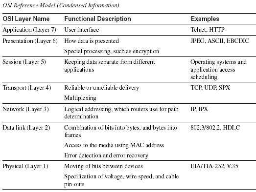
cours 2: The OSI model
The OSI model consists of seven layers, each of which can
(and typically does) have several sublayers.
The upper layers of the OSI model
(application, presentation, and session-Layers 7, 6, and 5)
are oriented more toward services to the applications.
The lower four layers
(transport, network,data link, and physical-Layers 4, 3, 2, and 1)
are oriented more toward the flows of data from end to end through
the network.
 top
top
cours 3: Types of Medium (Types de cables )
Unshielded Twisted Pair (UTP) Cable:
 The quality of UTP may vary from telephone-grade wire to extremely
high-speed cable. The cable has four pairs of wires inside the jacket.
Each pair is twisted with a different number of twists per inch
to help eliminate interference from adjacent pairs and other electrical
devices. The tighter the twisting, the higher the supported transmission
rate and the greater the cost per foot. The EIA/TIA (Electronic
Industry Association/Telecommunication Industry Association) has
established standards of UTP and rated five categories of wire.
Categories of Unshielded Twisted Pair
Type Use
Category 1 Voice Only (Telephone Wire)
Category 2 Data to 4 Mbps (LocalTalk)
Category 3 Data to 10 Mbps (Ethernet)
Category 4 Data to 20 Mbps (16 Mbps Token Ring)
Category 5 Data to 100 Mbps (Fast Ethernet)
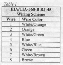
Unshielded Twisted Pair Connector (RJ-45 connector):
The standard connector for unshielded twisted pair cabling is an
RJ-45 connector. This is a plastic connector that looks like a large
telephone-style connector (See fig. 2). A slot allows the RJ-45
to be inserted only one way. RJ stands for Registered Jack, implying
that the connector follows a standard borrowed from the telephone
industry. This standard designates which wire goes with each pin
inside the connector.
The quality of UTP may vary from telephone-grade wire to extremely
high-speed cable. The cable has four pairs of wires inside the jacket.
Each pair is twisted with a different number of twists per inch
to help eliminate interference from adjacent pairs and other electrical
devices. The tighter the twisting, the higher the supported transmission
rate and the greater the cost per foot. The EIA/TIA (Electronic
Industry Association/Telecommunication Industry Association) has
established standards of UTP and rated five categories of wire.
Categories of Unshielded Twisted Pair
Type Use
Category 1 Voice Only (Telephone Wire)
Category 2 Data to 4 Mbps (LocalTalk)
Category 3 Data to 10 Mbps (Ethernet)
Category 4 Data to 20 Mbps (16 Mbps Token Ring)
Category 5 Data to 100 Mbps (Fast Ethernet)
Unshielded Twisted Pair Connector (RJ-45 connector):
The standard connector for unshielded twisted pair cabling is an
RJ-45 connector. This is a plastic connector that looks like a large
telephone-style connector (See fig. 2). A slot allows the RJ-45
to be inserted only one way. RJ stands for Registered Jack, implying
that the connector follows a standard borrowed from the telephone
industry. This standard designates which wire goes with each pin
inside the connector.
  Fig. 2. RJ-45 connector
Coaxial Cable & Connectors:
Coaxial cabling has a single copper conductor at its center. A plastic
layer provides insulation between the center conductor and a braided
metal shield (See fig. 3). The metal shield helps to block any outside
interference from fluorescent lights, motors, and other computers.
Fig. 2. RJ-45 connector
Coaxial Cable & Connectors:
Coaxial cabling has a single copper conductor at its center. A plastic
layer provides insulation between the center conductor and a braided
metal shield (See fig. 3). The metal shield helps to block any outside
interference from fluorescent lights, motors, and other computers.
  Fig. 3. Coaxial cable Fig. 4. BNC connector
Fiber Optic Cable:
Fiber optic cabling consists of a center glass core surrounded by
several layers of protective materials (See fig. 5). It transmits
light rather than electronic signals eliminating the problem of
electrical interference. This makes it ideal for certain environments
that contain a large amount of electrical interference. It has also
made it the standard for connecting networks between buildings,
due to its immunity to the effects of moisture and lighting.
Fig. 3. Coaxial cable Fig. 4. BNC connector
Fiber Optic Cable:
Fiber optic cabling consists of a center glass core surrounded by
several layers of protective materials (See fig. 5). It transmits
light rather than electronic signals eliminating the problem of
electrical interference. This makes it ideal for certain environments
that contain a large amount of electrical interference. It has also
made it the standard for connecting networks between buildings,
due to its immunity to the effects of moisture and lighting.
 Fig.5. Fiber optic cable
Ethernet Cable Summary:
Specification Cable Type Maximum length
10BaseT Unshielded Twisted Pair 100 meters
10Base2 Thin Coaxial 185 meters
10Base5 Thick Coaxial 500 meters
10BaseF Fiber Optic 2000 meters
100BaseT Unshielded Twisted Pair 100 meters
100BaseTX Unshielded Twisted Pair 220 meters
Wireless LANs:
Wireless LANs use high frequency radio signals, infrared light beams,
or lasers to communicate between the workstations and the file server
or hubs. Each workstation and file server on a wireless network
has some sort of transceiver/antenna to send and receive the data.
Information is relayed between transceivers as if they were physically
connected. For longer distance, wireless communications can also
take place through cellular telephone technology,microwave transmission,
or by satellite. Wireless LANs have several disadvantages. They
are very expensive, provide poor security, and are susceptible to
interference from lights and electronic devices. They are also slower
than LANs using cabling.
Vocabulary:
DHCP - (Dynamic Host Configuration Protocol) A protocol that is
run on a server that assigns one or all of the following to a
TCP/IP client: IP address, subnet (mask), default gateway,
DNS servers'IP addresses.
NAT - (Network address translation) Multiplexes traffic from the
internal network and present it to the Internet as if it was
coming from a single computer having only one IP address.
MicroSegmentation - Division of a network into smaller segments,
usually with the intention of increasing aggregate bandwidth to
network devices.
Collision Domain - In ethernet, the network area within which frames
that have collided are propagated. Repeaters and hubs
propagate collisions.
Installing Cable - Some Guidelines:
When running cable, it is best to follow a few simple rules:
· Always use more cable than you need. Leave plenty of slack.
· Test every part of a network as you install it. Even if
it is brand new, it may have problems that will be difficult to
isolate later.
· Stay at least 3 feet away from fluorescent light boxes
and other sources of electrical interference.
· If it is necessary to run cable across the floor, cover
the cable with cable protectors.
· Label both ends of each cable.
· Use cable ties (not tape) to keep cables in the same location
together.
Easy steps for creating patch cables:
When you are making a specific kind of connection it requires a
certain type of cable configuration. Patch cables are cables that
have standard connectors, often referred to as RJ-45 connectors,
on both ends of the cable. Although there are a many variations
of patch cables, there are three patch cable standard configurations
that are common in the industry.
· Straight-through cables: Used to connect end systems to
wall jacks, and active devices to patch panels ports (i.e. hubs,
switches, etc)
· Cross connect cables (a.k.a. cross-over): Used for connecting
two hubs/switches together or two active devices together.
· Roll Over cables: Many manufacturers use roll over cables
to connect a computer to the console port of a router, switch,
bridge or hub for management purposes. The configuration listed
in this document works with all cisco devices. For other
manufacturers refer to the specifications listed in their
documentation.
1. Cut the desired length of cable and typically leave a small amount
of slack.
2. Take the cable and strip off the sheath at each end (about 1
½ inches so you can manipulate the wires
3. Separate out each pair of wires (so it resembles a fan).
4. Using the charts below, arrange each individual wire and line
them up correctly, side by side, as close as possible with the
left most wire being the one to go in the left most slot of the
connector.This takes practice so be patient, and be sure to do
only one side of the cable at a time.
Fig.5. Fiber optic cable
Ethernet Cable Summary:
Specification Cable Type Maximum length
10BaseT Unshielded Twisted Pair 100 meters
10Base2 Thin Coaxial 185 meters
10Base5 Thick Coaxial 500 meters
10BaseF Fiber Optic 2000 meters
100BaseT Unshielded Twisted Pair 100 meters
100BaseTX Unshielded Twisted Pair 220 meters
Wireless LANs:
Wireless LANs use high frequency radio signals, infrared light beams,
or lasers to communicate between the workstations and the file server
or hubs. Each workstation and file server on a wireless network
has some sort of transceiver/antenna to send and receive the data.
Information is relayed between transceivers as if they were physically
connected. For longer distance, wireless communications can also
take place through cellular telephone technology,microwave transmission,
or by satellite. Wireless LANs have several disadvantages. They
are very expensive, provide poor security, and are susceptible to
interference from lights and electronic devices. They are also slower
than LANs using cabling.
Vocabulary:
DHCP - (Dynamic Host Configuration Protocol) A protocol that is
run on a server that assigns one or all of the following to a
TCP/IP client: IP address, subnet (mask), default gateway,
DNS servers'IP addresses.
NAT - (Network address translation) Multiplexes traffic from the
internal network and present it to the Internet as if it was
coming from a single computer having only one IP address.
MicroSegmentation - Division of a network into smaller segments,
usually with the intention of increasing aggregate bandwidth to
network devices.
Collision Domain - In ethernet, the network area within which frames
that have collided are propagated. Repeaters and hubs
propagate collisions.
Installing Cable - Some Guidelines:
When running cable, it is best to follow a few simple rules:
· Always use more cable than you need. Leave plenty of slack.
· Test every part of a network as you install it. Even if
it is brand new, it may have problems that will be difficult to
isolate later.
· Stay at least 3 feet away from fluorescent light boxes
and other sources of electrical interference.
· If it is necessary to run cable across the floor, cover
the cable with cable protectors.
· Label both ends of each cable.
· Use cable ties (not tape) to keep cables in the same location
together.
Easy steps for creating patch cables:
When you are making a specific kind of connection it requires a
certain type of cable configuration. Patch cables are cables that
have standard connectors, often referred to as RJ-45 connectors,
on both ends of the cable. Although there are a many variations
of patch cables, there are three patch cable standard configurations
that are common in the industry.
· Straight-through cables: Used to connect end systems to
wall jacks, and active devices to patch panels ports (i.e. hubs,
switches, etc)
· Cross connect cables (a.k.a. cross-over): Used for connecting
two hubs/switches together or two active devices together.
· Roll Over cables: Many manufacturers use roll over cables
to connect a computer to the console port of a router, switch,
bridge or hub for management purposes. The configuration listed
in this document works with all cisco devices. For other
manufacturers refer to the specifications listed in their
documentation.
1. Cut the desired length of cable and typically leave a small amount
of slack.
2. Take the cable and strip off the sheath at each end (about 1
½ inches so you can manipulate the wires
3. Separate out each pair of wires (so it resembles a fan).
4. Using the charts below, arrange each individual wire and line
them up correctly, side by side, as close as possible with the
left most wire being the one to go in the left most slot of the
connector.This takes practice so be patient, and be sure to do
only one side of the cable at a time.
 5. After, you have lined each of the wires according to the numbering
scheme, slide them into the connector (RJ-45 connector).The
connector should always have the copper lines facing upwards,
and the open end facing toward you. [hint: Inserting the wires
with a little downward pressure helps spread the wires out and
slide into the slots easier]
6. The wires must be inserted all the way so the copper tips can
be seen clearly from the front end of the connector (the tips are
butted up tightly against the end of the slot). The sheath should
be inside the connector about ¼ inch.
7. Now you have to crimp the wires using a Crimper tool. This is
completed by inserting the connector into the slot of the Crimper
tool (usually with the flap pointed downwards), and tightly
squeezing the handles together.
8. Complete steps 1-7 for the other side of the cable "Connector B".
9. Use a cable tester to test if your connections are correct.
top
5. After, you have lined each of the wires according to the numbering
scheme, slide them into the connector (RJ-45 connector).The
connector should always have the copper lines facing upwards,
and the open end facing toward you. [hint: Inserting the wires
with a little downward pressure helps spread the wires out and
slide into the slots easier]
6. The wires must be inserted all the way so the copper tips can
be seen clearly from the front end of the connector (the tips are
butted up tightly against the end of the slot). The sheath should
be inside the connector about ¼ inch.
7. Now you have to crimp the wires using a Crimper tool. This is
completed by inserting the connector into the slot of the Crimper
tool (usually with the flap pointed downwards), and tightly
squeezing the handles together.
8. Complete steps 1-7 for the other side of the cable "Connector B".
9. Use a cable tester to test if your connections are correct.
top
cours 4: IP addressing
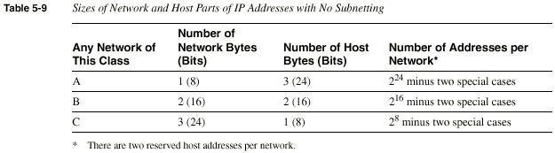
 Classes of Networks
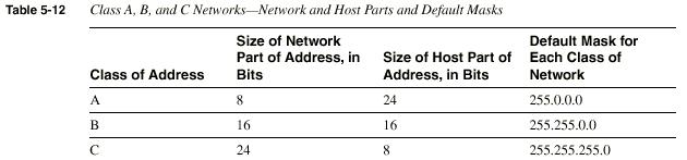
Class A, B, and C networks provide three network sizes. By definition,
all addresses in the same network have the same numeric value network
portion of the addresses. The rest of the address is called the host
portion of the address. Individual addresses in the same network all
have a different value in the host parts of the addresses but have
identical values in the network part.
Classes of Networks
Class A, B, and C networks provide three network sizes. By definition,
all addresses in the same network have the same numeric value network
portion of the addresses. The rest of the address is called the host
portion of the address. Individual addresses in the same network all
have a different value in the host parts of the addresses but have
identical values in the network part.
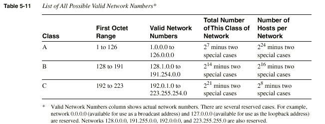
 Network numbers look like addresses (in dotted decimal format),
but they are not assignable to any interface as an IP address.
Conceptually, network numbers represent the group of all
IP addresses in the network. Numerically, the network number
is built with a nonzero value in the network part but with
all 0s in the host part of the network number.
Network numbers look like addresses (in dotted decimal format),
but they are not assignable to any interface as an IP address.
Conceptually, network numbers represent the group of all
IP addresses in the network. Numerically, the network number
is built with a nonzero value in the network part but with
all 0s in the host part of the network number.
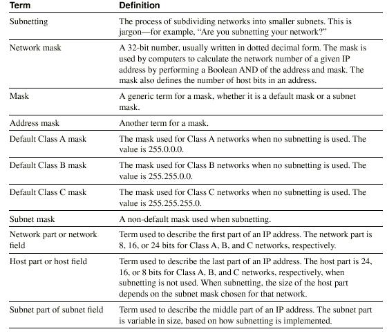
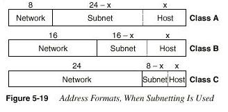 IP Grouping Concepts and Subnetting
Subnetting is simply the process of treating subdivisions of
a single Class A, B, or C IP protocols enforce the following
grouping concept: All hosts in the same group must not be
separated by an IP router. A corollary to the grouping concept
is this: Hosts separated by an IP router must be in separate
groups.The mask defines the number of host bits in the host part
of an address.
IP Grouping Concepts and Subnetting
Subnetting is simply the process of treating subdivisions of
a single Class A, B, or C IP protocols enforce the following
grouping concept: All hosts in the same group must not be
separated by an IP router. A corollary to the grouping concept
is this: Hosts separated by an IP router must be in separate
groups.The mask defines the number of host bits in the host part
of an address.
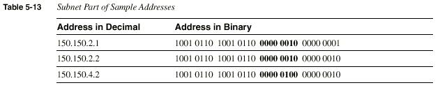 The example shows that the subnet field consists of bits
17 through 24 (the entire third byte).150.150.2.1 and 150.150.2.2
are in the same subnet because they are in the same Class B network
and because their subnet fields have the same value (0000 0010).
150.150.4.2 is in a different subnet of the same Class B network
because the subnet field has a different value than the first two
addresses (0000 0100). 150.150.4.2 must be physically located with at
least one IP router between itself and 150.150.2.1 and 150.150.2.2.
top
The example shows that the subnet field consists of bits
17 through 24 (the entire third byte).150.150.2.1 and 150.150.2.2
are in the same subnet because they are in the same Class B network
and because their subnet fields have the same value (0000 0010).
150.150.4.2 is in a different subnet of the same Class B network
because the subnet field has a different value than the first two
addresses (0000 0100). 150.150.4.2 must be physically located with at
least one IP router between itself and 150.150.2.1 and 150.150.2.2.
top
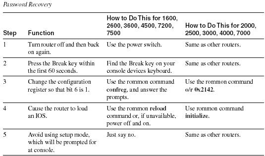
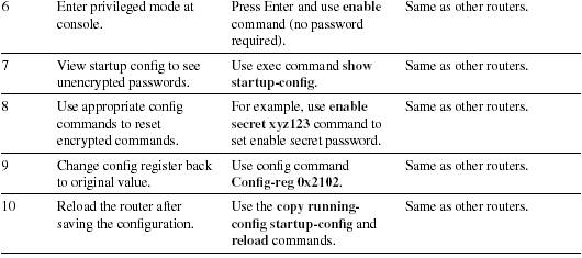
cours 5: password recovery
 top
more courses still to come , see you soon .....thanks
contact me here
top
more courses still to come , see you soon .....thanks
contact me here
|